
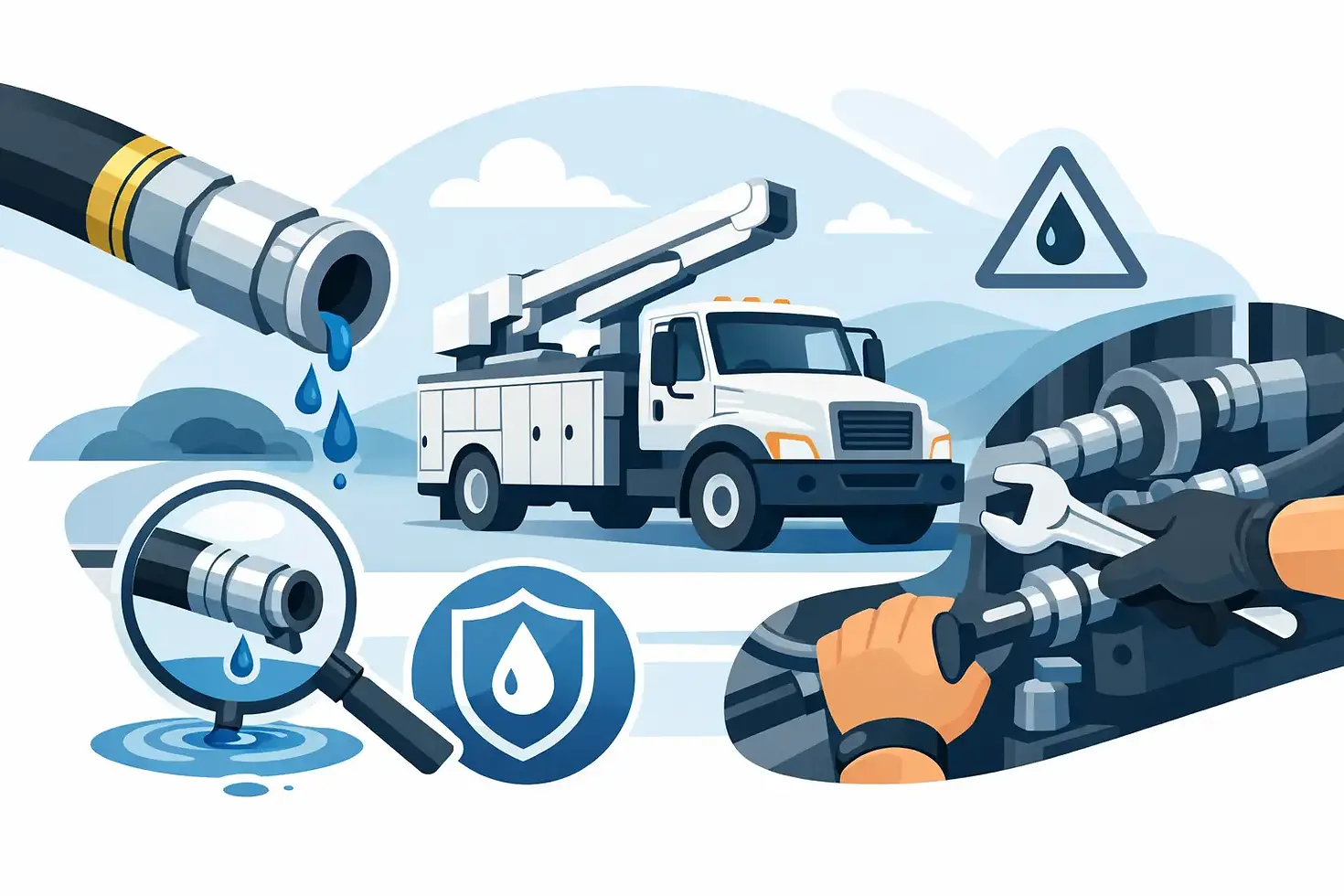
How to Prevent Hydraulic Leaks on Work Trucks

A hydraulic leak on a tipper body, refuse truck, trailer, or mining unit is rarely just a housekeeping issue. Lost oil can stop a vehicle, contaminate a worksite, damage components through low fluid levels, and create a safety risk around high-pressure lines. Knowing how to prevent hydraulic leaks starts before assembly, with the correct component specification, then continues through installation, commissioning, and disciplined inspection.
For fleet owners, body builders, and equipment buyers, the objective is not simply to choose a higher-priced hose or fitting. It is to build a hydraulic system in which pressure rating, fluid compatibility, routing, mounting, and service access all work together under actual operating conditions.
How to Prevent Hydraulic Leaks at the Design Stage
Most chronic leaks can be traced to a mismatch between the system duty and the parts selected. A component may be technically rated for the pressure on a drawing but still fail early when it is exposed to pressure spikes, vibration, heat, side loading, or poor routing. Dump truck and trailer hydraulics are especially demanding because cylinders, PTO pumps, hoses, and valves operate in a high-vibration environment with repeated load cycles.
Start with the full operating requirement, not only the maximum working pressure. Confirm normal operating pressure, relief-valve setting, expected pressure peaks, oil temperature range, pump flow, duty cycle, and the type of hydraulic fluid being used. The hose, fittings, seals, cylinders, valves, and pump must all be suitable for those conditions.
Pressure capability deserves particular attention. A line that is adequate at steady-state pressure may not tolerate transient spikes when a loaded body reaches the end of stroke, a valve shifts quickly, or an operator changes direction under load. Specify components with an appropriate safety margin and make sure the relief valve is correctly set and functioning. A relief valve that is adjusted too high can turn small installation weaknesses into repeated leaks.
Seal material is equally important. Nitrile, fluorocarbon, polyurethane, and other sealing materials each have different temperature and fluid-compatibility limits. The wrong seal may swell, harden, crack, or lose elasticity even when the cylinder or valve itself is correctly manufactured. This is particularly relevant when changing oil types or operating equipment in extreme heat or cold.
Select Hoses and Fittings as a Matched Assembly
Hoses and fittings should be treated as an assembly, not as interchangeable items purchased by thread size alone. The hose construction must meet the pressure, temperature, bend-radius, abrasion, and impulse requirements of the application. The fitting series, insert, ferrule, and crimp dimensions must match the hose manufacturer's requirements.
Mixing components from different systems can create an assembly that appears correct but has uncertain retention strength or sealing performance. For OEM production and fleet replacement programs, standardizing approved hose-and-fitting combinations reduces this risk and makes field service more consistent.
Thread identification is another frequent source of leakage. NPT, JIC 37-degree flare, ORFS, BSPP, BSPT, SAE straight thread, and metric connections can look similar at a glance, but they seal in different ways. Forcing a near-match connection may damage threads or create a joint that leaks only after vibration and thermal cycling.
Where the application allows it, choose connection types that are well suited to vibration and repeated service. ORFS fittings can provide dependable sealing in many mobile hydraulic applications because the O-ring face seal is less dependent on thread interference. JIC fittings remain widely used and practical, but the flare must be clean, undamaged, and correctly aligned. The best choice depends on the existing system standard, service environment, component availability, and the customer's maintenance capability.
Install for Movement, Vibration, and Service Access
Correct components will still leak if the installation places them under constant stress. Hoses need enough length to accommodate machine movement and pressure expansion, but not so much excess length that they rub, twist, or snag. A hose installed with a twist can experience premature reinforcement fatigue and fitting failure.
Observe the hose's minimum bend radius, particularly close to the fitting. Avoid bending a hose immediately at the coupling. Use suitable elbows or adapters where necessary so the hose can leave the port naturally rather than being forced into position.
Routing should keep hoses clear of exhaust systems, sharp edges, moving linkages, tires, driveshafts, and body pivot points. On tipping equipment, inspect hose movement throughout the full raise and lower cycle, not only when the body is resting on the chassis. A line may look properly routed in the parked position but stretch, pinch, or scrape at full extension.
Clamps and supports are essential, but over-clamping can also cause damage. Supports should control movement without crushing the hose or creating a hard abrasion point. Use protective sleeving, guards, or abrasion-resistant hose covers where contact cannot be fully avoided. On truck-mounted equipment, secure rigid tube runs appropriately and allow for vibration and thermal movement at connection points.
Cylinder ports require special care. Never use a hydraulic hose to pull a misaligned cylinder, valve, or pipe run into place. Side loading at a fitting can damage threads, distort a seal surface, and transfer vibration directly into the coupling. Align the components first, then make the connection.
Tightening Is Not the Same as Sealing
Overtightening is one of the most common and avoidable causes of hydraulic leakage. Excess torque can crack a flare, deform an O-ring, damage threads, or permanently distort a sealing face. Undertightening allows movement and leakage, but adding more force to a leaking connection is not a reliable repair method.
Use the specified torque for the fitting type and size. Lubrication requirements also matter because torque readings can change substantially depending on whether threads and sealing surfaces are dry, oiled, or coated with contaminants. Follow the fitting manufacturer's assembly procedure, including inspection of O-rings, backup rings, flare faces, and threads before installation.
Do not use thread sealant on connections that seal at an O-ring, cone, flare, or face. Sealant in the wrong location can contaminate the hydraulic system and may hide the actual cause of a poor connection. For tapered pipe threads, use an approved sealant sparingly and keep it away from the first thread to reduce the chance of material entering the oil circuit.
Control Contamination and Heat
Contamination does not always create an external leak immediately, but it accelerates the failures that cause one. Abrasive particles score cylinder rods and bores, damage valve spools, and cut sealing surfaces. Water contamination can promote corrosion and degrade oil performance. Dirty oil also causes components to operate inconsistently, which can increase pressure shocks and stress on fittings.
Use clean, capped components during storage and assembly. Flush new pipework where required, fill the system through suitable filtration, and replace filters according to the actual operating environment rather than only the calendar. A truck working in dusty quarry conditions needs a different inspection and filtration routine than a unit operating on paved urban routes.
Heat should be monitored as well. High oil temperature reduces viscosity and can harden or soften seals outside their intended range. It may indicate an undersized reservoir, restricted return line, incorrect valve setting, cooling deficiency, or a system being asked to work beyond its design duty. Fixing the heat source is more effective than repeatedly replacing seals.
Build Leak Checks Into Preventive Maintenance
A practical inspection program identifies wear before oil reaches the ground. Checks should be performed after initial commissioning, after hose replacement, after body or cylinder work, and at intervals suited to operating hours and environment. Operators are often the first people to see a developing issue, so their pre-start checks should be straightforward and specific.
Inspect these areas routinely:
Hose covers for abrasion, cracking, blistering, exposed reinforcement, flattening, or oil wetness.
Fittings and adapters for seepage, corrosion, damaged threads, and evidence of movement.
Cylinder rods for scoring, pitting, bent rods, damaged wipers, and oil around the gland.
Tube clamps, guards, and brackets for looseness, missing hardware, or metal-to-metal contact.
Reservoir level, fluid condition, filter indicators, and unusual temperature or pump noise.
Clean the equipment before inspection when possible. A fresh leak is much easier to locate on a clean valve bank, cylinder, or hose assembly than on a surface already covered with dust and old oil. Record recurring leak locations and component life. A repeated failure at the same point usually signals a routing, alignment, pressure, or specification problem, not bad luck.
Never search for a high-pressure hydraulic leak with a hand or finger. Fine oil jets can penetrate skin and require immediate emergency medical treatment. Use cardboard, wood, or an approved detection method, lower attachments or bodies safely, relieve pressure where required, and follow site lockout procedures before servicing.
Treat Repeated Leaks as a System Problem
Replacing the visibly leaking part may restore operation, but it does not always correct the root cause. If cylinder seals fail repeatedly, inspect rod condition, side loading, system pressure, and oil cleanliness. If hose fittings leak, verify fitting compatibility, torque, hose twist, vibration, and clamp placement. If a pump shaft seal leaks, check case drain conditions, inlet restrictions, reservoir breathing, and coupling alignment.
For custom truck bodies, trailers, and industrial equipment, hydraulic design should be reviewed alongside the fabrication layout. Bracket location, body movement, access panels, hose routing space, and component mounting all influence long-term reliability. Early coordination between the body builder, hydraulic supplier, and fleet buyer avoids expensive changes after equipment enters service.
The most dependable hydraulic systems are not necessarily the most complex. They are the systems specified for the real duty, assembled with matched components, installed without stress, and inspected before minor seepage becomes downtime. That discipline protects equipment availability, controls oil loss, and gives maintenance teams a system they can service with confidence.


Comments